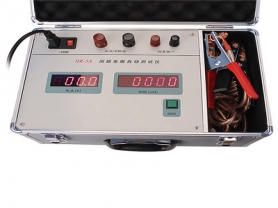
The transformer ratio and connection group tester is an instrument specifically used to measure the transformation ratio and connection group of transformers. It has a wide range of applications in fields such as power systems, electrical equipment manufacturing, and maintenance. By measuring the transformation ratio and connection group of a transformer, it ensures correct connection and operation, thereby safeguarding the safety and stability of the power system. The following is a detailed introduction to the transformer ratio and connection group tester:
Working Principle
The transformer ratio and connection group tester applies a known voltage or current to the primary side of the transformer, then measures the voltage or current on the secondary side to calculate the transformation ratio. At the same time, by analyzing the phase relationship of the transformer, it determines the connection group. The specific steps are as follows:
Apply voltage/current: Apply a known voltage or current to the primary side of the transformer.
Measure voltage/current: Simultaneously measure the voltage or current on the secondary side of the transformer.
Calculate transformation ratio: Calculate the transformation ratio based on the ratio of voltage or current between the primary and secondary sides.
Analyze phase relationship: Determine the connection group of the transformer by measuring the phase relationship between the primary and secondary sides.
Main Functions
Transformation ratio measurement: Measures the ratio of voltage or current between the primary and secondary sides of the transformer to ensure accuracy.
Connection group measurement: Determines the connection group of the transformer, such as Y/Y, Y/Δ, Δ/Y, etc.
Error measurement: Measures the ratio error and phase angle error of the transformer to evaluate its measurement accuracy.
Polarity test: Determines the polarity of the transformer to ensure correct connection.
Data recording: Built-in memory to store a large amount of measurement data for subsequent analysis.
Clear display: Usually equipped with a large LCD screen to display measurement results and operation menus.
Protection functions: Equipped with multiple protection functions to ensure the safety of equipment and personnel.
Communication interfaces: Usually equipped with USB, RS232, and other communication interfaces to connect with computers or other devices for data transmission and remote control.
Main Features
High precision: Uses high-precision sensors and measuring instruments to ensure accurate test results.
Multi-function: Capable of performing various transformer tests to meet different needs.
Automation: Supports automatic test modes, reducing manual intervention and improving test efficiency.
Portable design: Some models are designed to be portable for field use.
User-friendly: Provides an intuitive operation interface and rich function menus for user convenience.
Application Fields
Power systems: Used for factory testing, field testing, and maintenance of transformers to ensure performance and reliability.
Electrical equipment manufacturing: Used for quality control on transformer production lines to ensure product performance meets standards.
Electrical maintenance: Used for transformer repair and fault diagnosis to identify causes of performance degradation.
Scientific research: Used for transformer performance testing in scientific research to validate theoretical models.
Education and training: Used for teaching and training in electrical engineering to help students understand transformer testing methods and applications.
Usage Precautions
Safe operation: Strictly follow the equipment manual to ensure the safety of personnel and equipment.
Environmental requirements: Use in a dry, well-ventilated environment, avoiding moisture and high temperatures.
Regular calibration: Regularly calibrate the tester to ensure accurate measurement results.
Load matching: Ensure the transformer under test matches the range of the tester to avoid exceeding the range.
Cleaning and maintenance: Regularly clean the probes and connectors of the tester to ensure good contact.
Purchasing Suggestions
Accuracy requirements: Choose the appropriate accuracy level based on actual needs to ensure accurate test results.
Function configuration: Select a tester with corresponding functions based on testing needs, such as data storage, communication interfaces, etc.
Brand and quality: Choose well-known brands and high-quality products to ensure long-term stable operation.
Price and service: Consider price and after-sales service comprehensively to choose a cost-effective product.
Common Problems and Solutions
Inaccurate measurement results: Check if the tester is calibrated, if the probes and connectors are in good contact, and if the transformer under test is clean.
Equipment overheating: Check if the cooling system is normal, if there is any blockage or dirt, and ensure good ventilation.
Communication failure: Check if the communication cables are correctly connected and if the drivers are properly installed.
Specific Operation Steps
Preparation:
Confirm the type and parameters of the transformer under test.
Check the connections and settings of the tester to ensure all wiring is correct.
Ensure the safety of the test site and set necessary safety isolation measures.
Transformation ratio measurement:
Connect the primary and secondary sides of the tester to the primary and secondary sides of the transformer, respectively.
Start the tester and select the transformation ratio measurement mode.
Record the measurement results, including the ratio of voltage or current between the primary and secondary sides.
Connection group measurement:
Connect the primary and secondary sides of the tester to the primary and secondary sides of the transformer, respectively.
Start the tester and select the connection group measurement mode.
Record the measurement results, including phase relationship and connection group.
Error measurement:
Connect the primary and secondary sides of the tester to the primary and secondary sides of the transformer, respectively.
Start the tester and select the error measurement mode.
Record the measurement results, including ratio error and phase angle error.
End of test:
Gradually reduce the voltage or current until the tester is completely turned off.
Record the test results and analyze the performance of the transformer.
Disconnect the tester and restore the transformer to its normal state.
If you need to purchase or learn more about the transformer ratio and connection group tester, it is recommended to contact professional suppliers or manufacturers, who can provide more detailed technical parameters and application suggestions. I hope this information is helpful to you!