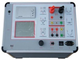
Test Transformer, also known as High-Voltage Test Transformer, is a special type of transformer specifically used for high-voltage insulation testing and withstand voltage testing of electrical equipment, insulating materials, etc. It differs from ordinary power transformers in that its design purpose is to generate extremely high voltages (typically from a few kilovolts to hundreds of kilovolts) in a short period to test the insulation performance of the tested object under high voltage, rather than for long-term power transmission. The following are the core knowledge points about test transformers: 1. Main Uses Insulation Withstand Voltage Test: Conduct AC or DC withstand voltage tests on various electrical equipment (such as cables, surge arresters, instrument transformers, switchgear, etc.) to verify whether their insulation strength meets standards. Partial Discharge Test: In conjunction with detection equipment, measure the partial discharge level of high-voltage equipment under operating voltage (industry standards have become stricter in 2026, typically requiring partial discharge levels to be controlled within 3pC). Leakage Current Test: Detect the leakage current of insulating materials under high voltage. Scientific Research and Teaching: Used for scientific research and teaching demonstrations in high-voltage laboratories. 2. Working Principle Test transformers operate based on the principle of electromagnetic induction. Structure: Mainly composed of an iron core, primary winding (low voltage), secondary winding (high voltage), and an insulation system. Process: The power frequency supply (50Hz/60Hz) is input to the primary winding through a voltage regulator, and due to the turns ratio (secondary turns far more than primary), a high voltage is induced in the secondary winding. Output: Can output AC high voltage, and if combined with a rectifier stack, can also output DC high voltage. 3. Differences from Ordinary Power Transformers Table Characteristic Test Transformer Ordinary Power Transformer Working State Short-time duty (usually a few minutes to tens of minutes) Long-term continuous operation Load Nature Mainly capacitive load (test objects are mostly capacitive) Mainly inductive or resistive load Transformation Ratio Extremely large (very high step-up ratio) Relatively small Short-circuit Impedance Large (to limit short-circuit current and protect equipment) Small (to reduce voltage drop and losses) Volume and Weight Relatively small (especially ultra-light designs) Larger, focusing on heat dissipation and efficiency Insulation Requirements Extremely high, must withstand overvoltage surges Designed according to rated voltage with some margin 4. Main Classifications