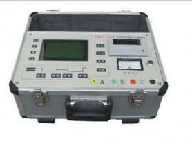
A DC Resistance Tester, commonly known as a direct resistance meter or transformer DC resistance tester in the power industry, is a precision instrument used to measure the DC resistance of inductive loads such as transformers, instrument transformers, generators, and motors.
It is one of the most effective means to detect defects such as poor winding welding quality, inter-turn short circuits, tap changer contact conditions, and broken conductor strands. It is a mandatory test item in preventive and acceptance tests for electrical equipment.
1. Core Functions and Detection Targets
By measuring the DC resistance of windings, the following hidden dangers can mainly be identified:
Inter-turn short circuits: Short circuits cause a significant decrease in the resistance of that phase.
Poor tap changer contact: Oxidation, burning, or insufficient pressure on contacts increases contact resistance, reflected in test data as abnormally high or unstable resistance at a specific tap position.
Poor lead welding: Cold solder joints or loose connections between windings and leads cause abnormal increases in resistance.
Broken conductor strands: If strands in multi-stranded conductors are broken, the effective cross-sectional area decreases, increasing resistance.
Three-phase unbalance: Comparing resistance values of three-phase windings, if the unbalance rate exceeds standards (typically phase-to-phase difference not greater than 2%, line-to-line difference not greater than 1%), it indicates one of the above defects.
2. Working Principle and Technical Challenges
Basic Principle
Uses the four-terminal measurement method (Kelvin bridge principle):
Current terminals (C1, C2): Output constant DC current flowing through the winding under test.
Voltage terminals (P1, P2): Measure the voltage drop across the winding.
Calculation: According to Ohm's law
R=U/I to calculate resistance. The four-terminal method eliminates the influence of test lead resistance and contact resistance, making it especially suitable for measuring low resistances (micro-ohm level).
Technical Challenge: Inductance Effect
Transformer windings are large inductive coils.
Problem: At the moment of energization, current cannot change abruptly and takes a long time to reach a stable value (charging time constant
τ=L/R is large). For large transformers, traditional methods may take several minutes or even over ten minutes to stabilize readings.
Solution: Modern DC resistance testers use constant current source high-speed charging technology and flux cancellation techniques (such as three-phase simultaneous testing, magnetization assist methods), reducing charging time from minutes to seconds or tens of seconds, greatly improving test efficiency.
3. Main Features
Multiple current output ranges: Provides multiple DC current ranges from 1mA to 100A (or even higher) to accommodate test objects of different capacities and resistance ranges.
Low currents for high resistance measurements (e.g., high-voltage side windings).
High currents for low resistance measurements (e.g., low-voltage side high-current windings) to improve anti-interference capability and resolution.
Three-phase simultaneous testing (high-end models):
Can apply current to three-phase windings simultaneously, using flux cancellation to significantly reduce charging time.
Can measure and calculate three-phase resistance values and unbalance rate in one test, directly determining pass/fail.
Automatic demagnetization: After testing, automatically performs reverse demagnetization to prevent residual magnetism in the core from affecting subsequent transformer operation (avoiding excessive inrush current).
Temperature conversion: Built-in temperature sensor or allows manual input of oil/winding temperature, automatically converting measured resistance to standard temperature (usually 75°C or 20°C) for historical data comparison.
Data storage and printing: Can store hundreds of test data sets, supports on-site report printing or upload to PC via USB/Bluetooth.
Protection functions: Includes back-EMF protection, overcurrent protection, overheat protection, and power-off protection to prevent damage to the instrument or test object in case of sudden power loss during testing.
4. Typical Application Scenarios
Transformers:
Measure DC resistance of windings at each tap position.
Check contact condition of on-load tap changers (OLTC) or off-circuit tap changers.
Instrument transformers: Measure primary and secondary winding resistance of current transformers (CT) and voltage transformers (PT).
Generators/Motors: Measure DC resistance of stator and rotor windings to check weld joints and inter-turn insulation.
Cables and busbars: Measure connection resistance of long-distance cable conductors or busbars to evaluate conductivity.
Switchgear: Measure contact resistance of circuit breaker conductive paths (although loop resistance testers are typically used, the principle is similar, and DC resistance testers can also be used for some low-voltage circuits).
5. Brief Operating Procedure
Preparation:
De-energize the test object and fully discharge (especially transformers that have just been in operation).
Disconnect or remove external connections to ensure measuring pure winding resistance.
Record ambient temperature or top oil temperature.
Wiring:
Use dedicated test leads to connect the instrument's I+, I- (current terminals) and V+, V- (voltage terminals) to the two ends of the winding under test.
Note: Voltage clips must be placed inside the current clips to eliminate lead resistance effects.
For three-phase transformers, select the appropriate test mode (e.g., single-phase test, three-phase test) based on the connection type (Y or Δ).
Parameter Setting:
Select appropriate current range (usually start with auto or middle range).
Set winding material (copper or aluminum) for temperature conversion.
Start Test:
Start the test; the instrument automatically charges, stabilizes current, and samples.
After readings stabilize, the instrument automatically locks the value and calculates unbalance rate.
Discharge and Disconnect:
After testing, the instrument automatically discharges. Wait until the discharge indicator disappears or the discharge completion sound is heard before removing test leads.
Warning: Inductive loads store significant energy; removing leads without discharge can produce high-voltage arcs, endangering personal safety and instrument life.
Data Analysis:
Compare three-phase resistance values and calculate unbalance rate.
Compare with factory values and historical data; changes should not exceed 2% (note temperature correction).
6. Result Evaluation Criteria (Reference)
Phase-to-phase difference: For transformers 1600kVA and below, phase-to-phase difference generally should not exceed 4%; above 1600kVA, phase-to-phase difference generally should not exceed 2% (if no neutral point is brought out, line-to-line difference should not exceed 1%).
Historical comparison: Compared with factory values at the same temperature or previous test values, change should not exceed 2%.
Tap changer: Resistance changes across all tap positions should be regular; if resistance at a certain position changes abruptly, it usually indicates poor contact at that tap.
7. Common Faults and Troubleshooting
Unstable/fluctuating readings:
Poor test lead contact (oxidized or loose clips).
Unstable contact of internal tap changer in the test object.
Strong external electromagnetic interference (need to avoid strong magnetic fields or switch to anti-interference mode).
Long charging time:
Winding inductance too large, current range too low (try increasing current range to shorten time constant).
Severe residual magnetism in core (need demagnetization first).
Display "open circuit" or "overload":
Winding is indeed open.
Test leads broken or incorrect wiring.
Selected current range too high for the resistance value (exceeds range).
Summary
The DC resistance tester is the "stethoscope" for power maintenance personnel, allowing insight into the internal connection health of core equipment like transformers through tiny resistance changes. Its test speed (especially fast charging capability for large transformers) and measurement accuracy are key indicators for evaluating instrument performance. Standardized operation (especially the discharge step) and accurate data analysis (temperature conversion and three-phase balance comparison) are essential to ensure test effectiveness.