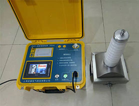
Handheld Zinc Oxide Arrester Live Tester
Handheld Zinc Oxide Arrester Live Tester, mainly used for testing the DC parameters of 6KV and 10KV zinc oxide arresters widely used in power systems, featuring simple wiring, small size, light weight, easy to carry, and can be connected to external power supply.
Product Features:
1. Multiple voltage reference signal sampling methods:
Wired Synchronization: Signal is taken from the metering winding at the PT end, transmitted via digital signal through wired connection.
Wireless Synchronization: Signal is taken from the metering winding at the PT end, transmitted via digital signal wirelessly, eliminating long cable connections.
Induction Plate Synchronization: No need to take signal from PT terminals; voltage signal is obtained from an induction plate installed at the base of phase B of the zinc oxide arrester.
No Voltage Synchronization: No need to take signal from PT terminals; voltage reference is found using software calculation.
2. Voltage and current signals (input impedance less than 1Ω) are completely isolated to ensure data reliability and safety.
3. The wireless three-phase zinc oxide arrester tester can test three phases simultaneously, with automatic calculation without compensation.
4. AC/DC dual-use, with built-in high-energy lithium-ion battery, especially suitable for places without power supply.
5. Zinc oxide arrester tester (bare wire 35KV), equipped with host computer software that can generate Word reports, facilitating data management and query;
6. Generating Word reports can intuitively tell you the condition of the zinc oxide arrester.
7. The instrument is controlled by a small computer, equipped with an 800×480 color LCD touch screen, high-speed printer, supports external mouse, and is easy to operate;
8. Handheld Zinc Oxide Arrester Live Tester, the instrument can automatically save 1000 sets of data internally, and can also save to an external USB drive.
Technical Specifications:
Reference voltage input range (peak): 10V-200V ±(reading × 2% + 5 digits)
Total leakage current measurement range (peak): 100uA-10mA ±(reading × 2% + 5 digits)
Resistive current measurement range (peak): 100uA-10mA ±(reading × 5% + 5 digits)
Capacitive current measurement range (peak): 100uA-10mA ±(reading × 5% + 5 digits)
Angle measurement range: 0°-360°
Power consumption: 4W
Charging power supply: DC12V
Lithium battery capacity: 10000mAh
Wireless transmission distance: 400M
Operating Steps:
Turn on the power switch, and the startup screen appears.
After a few seconds, the main menu appears as shown below (figure). The specific operation instructions for the main menu are as follows:
l Line Number: Press the "Function" key to move the cursor to "Line Number", press "OK" to enter; press the "Function" key to select the position to adjust, a small cursor will appear at this position; press the "Increase" and "Decrease" keys to select, after all positions are adjusted, press "OK".
l PT Ratio: Press the "Function" key to move the cursor to "PT Ratio", press "OK" to enter; press the "Function" key to select the position to adjust, a small cursor will appear at this position; then press the "Increase" and "Decrease" keys to select, after position adjustment is completed, press "OK".
l Test Phase Sequence: Press the "Function" key to move the cursor to "Test Phase Sequence", press "OK" to enter; press the "Function" key to select the position to adjust, a small cursor will appear at this position; press the "Increase" and "Decrease" keys to select, after position adjustment is completed, press "OK". Among them, A, B, C represent single-phase measurement, X represents three-phase simultaneous measurement.
l Compensation Angle: Adjustment method is the same as above. Generally, the influence of inter-phase interference is about 2°~5°. Since it is difficult to accurately calculate the interference amount, hard compensation is generally not recommended, but it is set to 0.0°. You can compare the data trend over a period of time according to regulations. If you need to adjust the edge phase correction angle, refer to the relevant chapters in "Measurement Principle" later. If three-phase simultaneous measurement is selected, the angle is automatically compensated.
l Date: Adjustment method is the same as above. Use the "Function" key to select the item to adjust: year, month, day, hour, minute, second, use the "Increase" and "Decrease" keys to adjust, after all adjustments are completed, press "OK".
l Mode: Press "OK" to switch between wired, induction, and wireless modes.
l View: Press the "Function" key to move the cursor to "View", press "OK" to enter (as shown in Figure 6); press the "Increase", "Decrease", and "Function" keys to select the data to view, press "OK" to display that set of data;
l Measurement: Press the "Function" key to move the cursor to "Test", press "OK" to enter measurement, and the measurement screen as shown in Figure 7 appears.
Display: Switch the display screen to show all test information or a brief display. If three-phase simultaneous measurement is selected, press "Increase" and "Decrease" to cycle through the information of the three phases.
Print: Can print the measured data, but does not store it.
Store: Store the current data, select the storage location for the data, and press "OK" to save.
Exit: Exit measurement and return to the system main menu.
7. Data Upload: Install the data communication packaging software provided with the instrument on the computer, and use a serial communication cable to connect the instrument to the computer's RS-232 serial port. Turn on the instrument power, run the communication program on the computer, click the desired function on the computer, and complete the relevant operations.