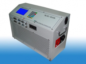
Technical Features of Three-Phase Multifunctional Capacitance and Inductance Tester
- August 16, 2019 08:06 Source: Yangzhou Dairui Co., Ltd.
Technical Features of Three-Phase Multifunctional Capacitance and Inductance Tester
I. Overview: The Capacitance and Inductance Tester is mainly used for measuring high-voltage shunt capacitor banks in reactive power compensation devices, as well as reactors. Its measurement basis complies with the national standard SJ-255-10300 for capacitance measuring instruments. It is specially developed to address the problems existing in on-site measurement of high-voltage shunt capacitor banks in substations. It mainly solves the following problems:
△ On-site measurement of capacitors without removing connecting wires, simplifying the testing process, effectively improving work efficiency, and avoiding damage to power equipment;
△ Complete parameter measurement, making it easy to judge the quality changes of capacitors and faults in inter-component connecting conductors;
△ Large-capacity data storage and USB communication, eliminating the need for on-site manual data recording, ensuring the integrity of measurement data;
II. Features of the Measuring Instrument:
△ The instrument adopts advanced measurement principles and four-terminal measurement technology, ensuring good measurement repeatability and test repeatability;
△ Large-screen LCD display (320X240 dot matrix) with Chinese menu prompts for operation;
△ The LCD screen comes with built-in touch keys, making operation intuitive and simple;
△ Automatic segmented current compensation linearizes the full-scale current, improving the measurement accuracy of the instrument;
△ Ambient temperature monitoring facilitates the assessment of the influence of temperature on capacitance values;
△ The new-generation USB communication function simplifies connection to PCs, facilitating the transmission and management of measurement data;
III. Parameters for Detection:
Capacitors
1. Capacitance value C | 2. Voltage value U | 3. Current value I | 4. Frequency value F | 5. Active power P |
7. Reactance value XC | 8. Resistance value R | 9. Phase angle φ | 6. Reactive power Q |
Inductors
1. Inductance value L | 2. Voltage value U | 3. Current value I | 4. Frequency value F | 5. Active power P |
7. Reactance value XL | 8. Resistance value R | 9. Phase angle φ | 6. Reactive power Q |
IV. Equivalent Circuit Modes:
Internal series and parallel equivalent circuit diagrams for RC
, where Cx is the actual capacitance, Rs is the lead resistance, Lo is the lead inductance, Rp is the inter-electrode insulation resistance, and Co is the inter-electrode distributed capacitance. Actual inductors, capacitors, and resistors are not ideal reactance or resistance elements but present as complex impedance elements in series or parallel form. This instrument calculates the required values based on series or parallel equivalent circuits. Different equivalent circuits will yield different results, and the difference depends on the component. Generally, for low-impedance components (mainly high-value capacitors and low-value inductors), the series equivalent circuit is used. Conversely, for high-impedance components (mainly low-value capacitors and high-value inductors), the parallel equivalent circuit is used. According to actual on-site usage, there are only two cases: (1) To test the internal quality changes of the device, select the equivalent mode as "Parallel Equivalent"; (2) To test the resistance changes of the external connecting wires of the device, select the equivalent mode as "Series Equivalent".
V. Technical Parameters of the Instrument:
◆ Normal working conditions of the instrument
△ Ambient temperature: -10℃ to +40℃;
△ Relative humidity: ≤90%;
△ Working power supply: 220V±10% at power frequency;
△ Rated frequency: 50Hz;
△ Rated output: 22V/2A/500VA;
△ Instrument dimensions: 420×170×340mm (width×height×depth);
△ Weight: approximately 10kg;
VI. Measurement Range, Resolution, and Error Values:
Capacitance measurement ranges: | Error values: |
(1) 0.010μF to 0.200μF; | ±0.5%; |
(2) 0.200μF to 2.000μF; | ±0.5%; |
(3) 2.000μF to 20.00μF; | ±0.5%; |
(4) 20.00μF to 200.0μF; | ±0.5%; |
(5) 200.0μF to 3300.μF; | ±0.5%; |