

This entry lacks an information box. Please supplement relevant content to make the entry more complete and quickly upgrade it. Come on!
High Voltage Switch Mechanical Dynamic Characteristic Tester is designed based on the latest "High Voltage AC Circuit Breakers" GB1984-2003, and refers to the People's Republic of China electric power industry standard "General Technical Conditions for High Voltage Test Equipment" Part 3, DL/T846.3-2004 as the design basis. It provides convenience for dynamic analysis of various types of circuit breakers and can accurately measure the mechanical dynamic characteristic parameters of high voltage circuit breakers such as low oil, multi-oil, vacuum, and SF6 at various voltage levels. High voltage circuit breakers play dual roles of control and protection in the power system, and their performance directly affects the safe operation of the power system. Mechanical characteristic parameters are one of the important parameters for judging the performance of circuit breakers.
Table of Contents
- 1 Product
- Introduction
- 2 Main Features
- 3 Technical Specifications
- 4 Term Definitions
- 5 Printer Installation Method
Product Introduction
Our company's High Voltage Switch Characteristic Tester is based on the latest High Voltage AC Circuit Breakers GB1984-2003 as the design blueprint, referring to the People's Republic of China
High Voltage Switch Mechanical Dynamic Characteristic Tester
National Electric Power Industry Standard "General Technical Conditions for High Voltage Test Equipment" Part 3, DL/T846.3-2004 High Voltage Switch Comprehensive Tester as the design basis. It provides convenience for dynamic analysis of various types of circuit breakers and can accurately measure the mechanical dynamic characteristic parameters of high voltage circuit breakers such as low oil, multi-oil, vacuum, and SF6 at various voltage levels, including closing (opening) sequence, maximum closing (opening) time, three-phase non-simultaneity, same-phase non-simultaneity, closing (opening) time, action time, bounce time, bounce count, bounce amplitude, travel, open distance, overtravel, overtravel, just-closing (opening) speed, maximum speed, average speed, gold short time, no-current time, current waveform curve (dynamic), time-travel-speed dynamic curve (ms), time-travel-speed dynamic curve (mm), etc.
Main Features
>Can perform electric operation and manual operation
>Suitable for mechanical dynamic characteristic testing of various high voltage circuit breakers within 500KV voltage level
>Can measure actual travel and custom travel
>Can achieve single close, single open, close-open, reclose, and reopen operations of circuit breakers
>Easy wiring and simple operation. Only one close (open) action is needed to obtain all data for close (open). Can choose to save 50 sets of data, provide later query and upload to computer for permanent storage, and can also view and print all data and motion curve diagrams on-site
>Built-in clock circuit can display current year, month, day, hour, minute, second. Even if power is off, it can automatically save setting data and test data
>Built-in delay protection function. After the circuit breaker operates, it can automatically cut off the action power supply, well protecting the circuit breaker equipment and the high voltage switch tester
>The instrument has built-in DC power supply with selectable range: 30-270V/10A. There is no voltage drop at the moment of output of conventional rectifier power supply, making it very accurate for testing switch action voltage
>Can dynamically analyze the relationship between travel, speed, and time for each 1ms of the circuit breaker
>Can be configured with upload software to achieve computer archiving, online viewing, and printing.
Technical Specifications
>Time test range: 1—499.9ms Resolution: 0.01ms Accuracy ≤0.1ms
>Speed test range: 15ms Resolution: 0.01m/s Accuracy ±1% reading + 2 digits
>Travel test range: Unlimited Resolution: 0.01mm Accuracy ±1% reading + 2 digits
>DC power supply selection range: 25-265V/10A Resolution: 1V Accuracy ≤±1%
>Working power supply: AC220V ±10% Frequency: 50Hz ±5%
>Ambient temperature: -10°C~40°C Relative humidity: ≤85%
>Insulation resistance: ≤2MΩ
>Dielectric strength: Power input to chassis can withstand 1.5KV for 1 minute withstand voltage test.
Term Definitions
1. Closing/Opening time: The time interval from the instant the closing (opening) command is received to the instant when all pole contacts touch (separate). 2. Closing/Opening simultaneity: The maximum time difference between the instants of contact touch (separation) among the breaks. 3. Bounce time: The time from the first contact (separation) to the final stable contact (separation) of the moving and static contacts during closing (opening) operation. 4. Action time: (Contact action time) The time from the instant the closing (opening) command is received to the instant when the contacts just start to move. 5. Bounce count: The number of times the moving and static contacts separate (close) during opening (closing) operation. 6. Bounce amplitude: The maximum rebound value of the moving contact during its movement. 7. Travel: The distance from the initial position to any position of the moving contact during opening and closing operations. 8. Open distance: The total gap between the contacts of one pole or any connected conductive parts when in the open position. 9. Overtravel: The distance the moving contact continues to move after the contacts touch during closing operation. 10. Overthrow: The difference between the maximum travel during the movement of the moving contact and the stable travel after operation during opening and closing operations. 11. Just-closing (opening) speed: The speed of the moving contact at the instant of contact (separation) with the static contact during closing (opening) operation. 12. Average speed: The ratio of the travel to the time during the entire movement of the moving contact in closing (opening) operation. 13. Gold short time: In close-open operation, the time interval from the instant when all pole contacts touch to the instant when all pole arc contacts separate in the subsequent opening operation.
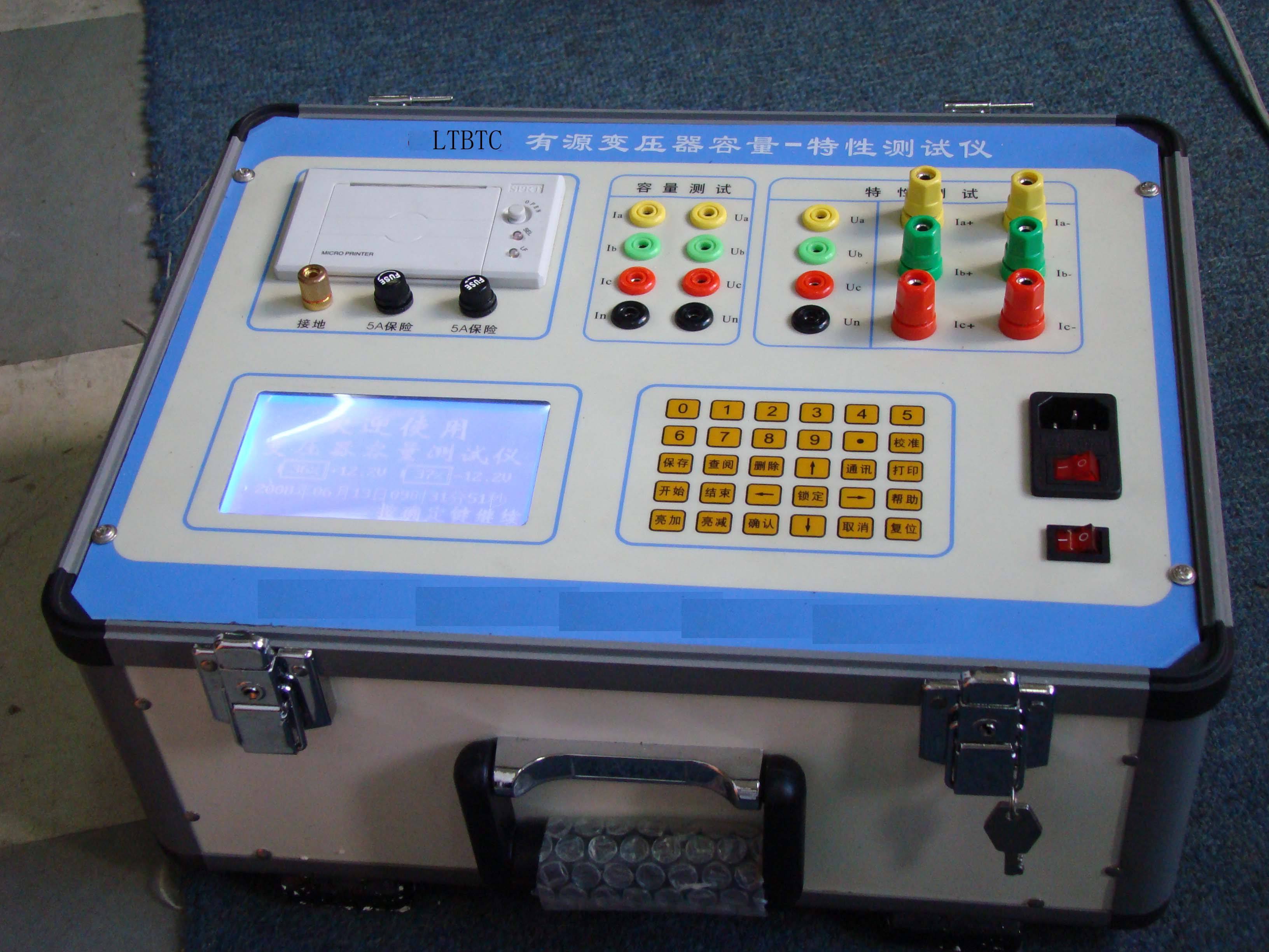
(1) A-type panel: Please pinch the elastic clips on both sides of the printer frame with your hand, push the entire printer into the mounting hole of the instrument or equipment panel, and check whether the printer is firmly installed. (2) D-type and F-type front paper-loading panel type: Installation is extremely simple and convenient. Insert the entire printer into the mounting hole of the instrument or equipment panel, clamp the printer from behind the equipment panel with the plastic clips and tighten the screws. ◆General paper loading process is as follows ① Remove the front cover of the printer ② A-type panel micro printer must be removed from the instrument panel. Note: The micro printer power must be turned off before operation. D-type, F-type front paper-loading panel type, and T-type desktop can skip this step. ③ Remove the paper roll shaft, install a new paper roll, place the paper shaft back into the guide slot of the printer, and confirm that the paper roll shaft is firmly installed and will not fall out. ④ Cut the paper end into a triangle or trim it neatly. ⑤ Turn on the printer power. After the printer feeds a little paper, press the SEL key to turn off the SEL indicator light, then press the LF key to rotate the print head. Use your hand to feed the paper head into the paper inlet below the print head. The paper will slowly enter the print head until it comes out from the front of the print head. Then press the LF or SEL key to stop the print head rotation → cover the printer cover, and thread the paper out through the paper outlet of the front cover. ◆Replacing the ribbon cartridge Ribbon replacement is only for dot matrix printers. Thermal printers only need special thermal paper and do not require ribbon replacement (consumables). Note: Thermal paper has two sides, and only the front side can be printed. ◆The process of replacing the ribbon cartridge is as follows ① Open the printer front cover. ② First lift the right end of the ribbon cartridge, then lift the left end (the end with the knob) to remove the ribbon cartridge. ③ Gently place the left end of the new ribbon cartridge on the gear shaft of the print head, turn the knob on the ribbon cartridge in the direction of the arrow until the cartridge end falls to the bottom, then put down the right end of the ribbon cartridge. ④ Install the printer cover. First hang the upper part of the front cover on the frame, pay attention to aligning the indicator lights and buttons, then press the lower part of the front cover toward the frame with a little force to snap the front cover onto the frame.
