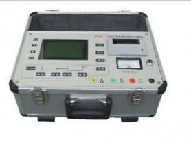
Overview of Ultrasonic Partial Discharge Inspection Instruments
Introduction
High-voltage electrical equipment in power systems (such as transformers, switchgear, cable joints, etc.) may experience partial discharge (PD) phenomena during long-term operation due to manufacturing defects, aging, moisture, and other reasons. Partial discharge not only reduces the insulation performance of equipment but can also lead to serious faults or even safety accidents. Therefore, regular detection and assessment of partial discharge conditions in power equipment are crucial for preventing power accidents. Ultrasonic partial discharge inspection instruments, as an effective detection tool, play an important role in the maintenance of power systems.
Working Principle
The working principle of the ultrasonic partial discharge inspection instrument is based on the ultrasonic signals generated during partial discharge. When partial discharge occurs inside power equipment, ultrasonic signals with frequencies higher than 20kHz are generated. These signals can propagate to the external environment through gaps, holes, and other openings on the equipment surface. The ultrasonic partial discharge inspection instrument can receive these signals and convert them into audible audio signals or display them on a screen, thereby helping technicians determine the presence and possible location of partial discharge.
Features and Functions
High detection sensitivity: Capable of detecting weak ultrasonic signals.
Large sample capacitance coverage: Suitable for various electrical equipment with different capacities.
Wide range of applicable samples: Can be used to detect various high-voltage electrical equipment such as transformers, switchgear, and cable joints.
Multi-functional integration: In addition to basic ultrasonic detection, some advanced devices also have laser positioning, image acquisition, waveform recording, and other functions.
Intelligent cloud system support: Some high-end models of inspection instruments can connect to cloud servers via wireless networks for remote monitoring and data analysis.
Application Scenarios
Power systems: Monitor the operating status of high-voltage electrical equipment to prevent faults caused by partial discharge.
Railway systems: Used for inspection of electrified equipment along railway lines to ensure the safety of train operations.
Industrial facilities: Used for detection of power equipment in factories to prevent production interruptions caused by unexpected power outages.
Usage Precautions
Environmental factors: Ensure there are no other strong sound sources interfering during detection.
Operating skills: Familiarize yourself with the equipment's operation manual and master the correct usage methods.
Maintenance: Regularly check the working status of the equipment and keep the sensor clean.
Data analysis: Correctly interpret detection data, and consult professionals for in-depth analysis when necessary.
Conclusion
Ultrasonic partial discharge inspection instruments, with their unique detection principles and technical advantages, have become one of the indispensable tools for power equipment maintenance. Through regular inspections, power accidents caused by partial discharge can be effectively prevented and reduced, ensuring the safe and stable operation of power systems. In the future, with technological advancements, such equipment will become more intelligent and portable, providing stronger technical support for the maintenance of power systems.
I hope this article can provide you with a comprehensive understanding of ultrasonic partial discharge inspection instruments. If you have any specific questions or need further information, please feel free to let me know.
Related Links · 9
Dielectric Loss Tester Articles
Search Completed
Of course. Below is an overview of an article about the dielectric loss tester, covering its working principle, operating steps, technical features, and usage precautions.
Dielectric Loss Tester
Introduction
The dielectric loss tester is a high-precision testing instrument used to measure the energy loss of dielectrics under AC voltage. This loss is mainly caused by the polarization and conductivity of the dielectric. Dielectric loss testers are widely used in preventive maintenance of power equipment, such as dielectric loss testing of high-voltage equipment like generators, transformers, cables, and instrument transformers, to assess their insulation status.
Working Principle
The working principle of the dielectric loss tester is to measure the electrical energy consumed by the dielectric under AC voltage, which is converted into heat energy causing loss. The instrument's measurement circuit includes a standard circuit and a test circuit. The standard circuit consists of a built-in high-stability standard capacitor and the measurement circuit, while the test circuit consists of the test object and the measurement circuit. By measuring the amplitude and phase of the current in the standard circuit and the test circuit separately, and using a microcontroller with digital real-time acquisition methods and vector operations, the capacitance value and dielectric loss tangent of the test object can be obtained.
Technical Features
High-precision measurement: Uses advanced measurement techniques and algorithms to ensure the accuracy of test results.
Integrated structure: The instrument integrates components such as the dielectric loss test bridge, variable frequency voltage-regulating power supply, and step-up transformer, making it convenient for field use.
Safety protection: Built-in multiple safety protection mechanisms such as overvoltage protection and overcurrent protection to ensure the safety of operators and equipment.
Automatic voltage boost control: The built-in boosting device can automatically adjust the output voltage, simplifying the operation process.
Operating Steps
Pre-measurement preparation:
Connect one end of the grounding wire to the instrument's grounding terminal and the other end to a reliable earth ground to ensure the instrument's shell is at ground potential.
For normal wiring, insert the high-voltage cable plug into the rear HV socket, connect the grounding end of the high-voltage cable to the grounding terminal, and clamp the red crocodile clip at the other end to the lead of the test object. The red crocodile clip and the black crocodile clip are used in parallel.
Insert the CX low-voltage cable into the CX socket, connect the red clip at the other end to the low end or end screen of the test object, and the black clip to ground, leave it floating, or connect it to a shielding device.
Start the test:
Select the appropriate test voltage based on the characteristics of the test object.
Start the test program, and the instrument will automatically boost the voltage and perform the test on the test object.
Read results:
Read parameters such as the dielectric loss tangent and capacitance value from the instrument's display screen.
For some complex tests, multiple tests may be required, and the average value can be calculated to improve accuracy.
Data saving and analysis:
Test data can be saved in the instrument or transferred to a computer via USB interface for subsequent analysis.
Usage Precautions
Safety first: Operators should ensure they understand safety regulations before using the dielectric loss tester, especially those involving high-voltage operations.
Reliable grounding: Ensure the instrument is reliably grounded before use.
Insulation testing: Technical personnel should perform insulation testing on the equipment to avoid accidents during operation.
Correct selection of boost gear: Before testing, determine the voltage withstand level of the equipment and correctly select the boost gear of the tester to prevent equipment breakdown.
Avoid sudden power off: After the tester is started, unless there are special circumstances, do not suddenly turn off the power to avoid overvoltage damage to the equipment.
Conclusion
The dielectric loss tester is one of the indispensable tools in power system maintenance. It helps technical personnel accurately assess the insulation status of power equipment and prevent faults caused by poor insulation. With technological advancements, future dielectric loss testers will become more intelligent and portable, providing stronger technical support for the maintenance of power systems.
I hope this article can provide you with a comprehensive understanding of dielectric loss testers. If you have any specific questions or need further information, please feel free to let me know.