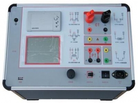
The test transformer operates based on the principle of electromagnetic induction. Structure: mainly composed of iron core, primary winding (low voltage), secondary winding (high voltage), and insulation system. Process: The power frequency power supply (50Hz/60Hz) is input to the primary winding through a voltage regulator, and high voltage is induced in the secondary winding by utilizing the turns ratio (secondary turns far more than primary). Output: It can output AC high voltage, and if combined with a rectifier silicon stack, it can also output DC high voltage. 3. Differences from ordinary power transformers Table Characteristics Test Transformer Ordinary Power Transformer Working State Short-time duty (usually a few minutes to tens of minutes) Long-term continuous operation Load Nature Mainly capacitive load (test objects are mostly capacitive) Mainly inductive or resistive load Turns Ratio Extremely large (very high step-up ratio) Relatively small Short-circuit Impedance Larger (limits short-circuit current, protects equipment) Smaller (reduces voltage drop and losses) Volume and Weight Relatively small (especially ultra-light design) Larger, focusing on heat dissipation and efficiency Insulation Requirements Extremely high, must withstand overvoltage surges Designed according to rated voltage with certain margin 4. Main Classifications By insulation medium: Oil-immersed test transformer: traditional type, good insulation performance, good heat dissipation, but large volume, heavy weight, prone to oil leakage. Dry-type test transformer: oil-free, fireproof and explosion-proof, small volume, light weight, suitable for indoor and mobile testing. Gas-insulated (SF6) test transformer: extremely high insulation strength, very small volume, commonly used for ultra-high voltage testing. By structure: Single-stage test transformer: suitable for general voltage levels (e.g., below 100kV). Cascade test transformer: multiple transformers connected in series to obtain higher output voltage (e.g., 300kV, 500kV and above). New trends (2026 perspective): Ultra-light test transformer: adopts new insulation materials and optimized design, significantly reducing weight, easy for single-person handling, adapting to field substation acceptance needs. Low partial discharge design: for new energy and UHV acceptance, partial discharge level is extremely low (<3pC), ensuring accuracy of test data. 5. 2026 Industry Technology Trends According to the latest industry reports, the development of test transformers is undergoing a technological leap from "usable" to "easy-to-use": Low Partial Discharge: With the increasing reliability requirements of power grids for equipment, the partial discharge level of the test transformer itself has become a core indicator. Mainstream requirements have tightened from 5pC to 3pC or even lower to avoid interfering with the test results of the tested object. Lightweight and Portability: To adapt to outdoor mobile testing and acceptance of distributed energy stations, equipment is developing towards "single-person portable" direction, with ultra-light dry-type transformers becoming mainstream. Anti-cracking and High Reliability: To address the issue of traditional coils being prone to cracking, new casting processes and structural designs are adopted to enhance mechanical stability during frequent voltage rise and fall. Intelligent Integration: Modern test transformers are often integrated with control boxes and measurement systems, featuring automatic voltage rise, data recording, fault diagnosis, and other functions. 6. Usage Precautions Grounding Safety: The casing and base must be reliably grounded to prevent high-voltage back-strike. Voltage Rise Speed: Voltage rise should be uniform and slow; impact closing or rapid voltage rise is strictly prohibited. Environmental Requirements: Keep the test site dry and clean to avoid surface flashover. Discharge Operation: After the test, fully discharge the test object and the transformer output terminal using a discharge rod before dismantling wires.