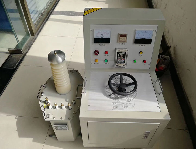
Wired Zinc Oxide Arrester Resistive Current Tester
Product Features
1. High current handling capability
This is mainly reflected in the arrester's ability to absorb various lightning overvoltages, power frequency transient overvoltages, and switching overvoltages. The current handling capability of zinc oxide arresters fully meets or even exceeds national standards. Indicators such as line discharge class, energy absorption capability, 4/10 nanosecond high current impulse withstand, and 2ms square wave current handling capability have reached the domestic leading level.
2. Excellent protective characteristics
Zinc oxide arresters are electrical products used to protect various electrical equipment in power systems from overvoltage damage, with good protective performance. Because the nonlinear volt-ampere characteristics of zinc oxide valve plates are excellent, only a few hundred microamperes of current pass through under normal operating voltage, making it easy to design a gapless structure, which gives it the characteristics of good protective performance, light weight, and small size. When overvoltage intrudes, the current flowing through the valve plate increases rapidly, while limiting the amplitude of the overvoltage and releasing the energy of the overvoltage. After that, the zinc oxide valve plate returns to a high-resistance state, allowing the power system to operate normally.
3. Good sealing performance
The arrester components use high-quality composite outer jackets with good aging resistance and air tightness. Measures such as controlling the compression of sealing rings and applying additional sealing adhesive are adopted, with ceramic outer jackets as sealing materials, ensuring reliable sealing and stable performance of the arrester.
4. Mechanical performance
Mainly consider the following three factors:
(1) Earthquake force it can withstand;
(2) Maximum wind pressure acting on the arrester;
(3) Maximum allowable tensile force of the conductor borne by the top of the arrester.
5. Good anti-pollution performance
Gapless zinc oxide arresters have high pollution resistance.
The creepage distance ratio levels specified by national standards are:
Class II Medium pollution area: creepage distance ratio 20mm/kV
Class III Heavy pollution area: creepage distance ratio 25mm/kV
Class IV Extra heavy pollution area: creepage distance ratio 31mm/kV
6. High operational reliability
The reliability of long-term operation depends on the quality of the product and whether the product selection is reasonable. The product quality that affects it mainly includes the following three aspects:
(1) The rationality of the overall structure of the arrester;
(2) The volt-ampere characteristics and aging resistance of zinc oxide valve plates;
(3) The sealing performance of the arrester.
7. Power frequency withstand capability
Due to various reasons in the power system such as single-phase grounding, long-line capacitance effect, and load shedding, power frequency voltage rise or transient overvoltages with high amplitude can occur. The arrester has the ability to withstand a certain power frequency voltage rise for a certain period of time.
Operating Steps
Turn on the power switch, and the startup screen appears.
After a few seconds, the main menu (as shown in the figure) appears. The specific operation instructions for the main menu are as follows:
l Line number: Press the "Function" key to move the cursor to "Line number", press "OK" to enter; press the "Function" key to select the position to adjust, a small cursor will appear under this position; press the "Increase" and "Decrease" keys to select, after all positions are adjusted, press the "OK" key.
l PT ratio: Press the "Function" key to move the cursor to "PT ratio", press "OK" to enter; press the "Function" key to select the position to adjust, a small cursor will appear under this position; then press the "Increase" and "Decrease" keys to select, after the position adjustment is completed, press the "OK" key.
l Test phase sequence: Press the "Function" key to move the cursor to "Test phase sequence", press "OK" to enter; press the "Function" key to select the position to adjust, a small cursor will appear under this position; press the "Increase" and "Decrease" keys to select, after the position adjustment is completed, press the "OK" key. Among them, A, B, C represent single-phase measurement, X represents three-phase simultaneous measurement.
l Compensation angle: The adjustment method is the same as above. Generally, the influence of inter-phase interference is about 2° to 5°. Since it is difficult to accurately calculate the interference amount, hard compensation is generally not recommended. Instead, it is set to 0.0°. According to the regulations, the data change trend over a period of time can be compared longitudinally. If you need to adjust the side phase correction angle, refer to the relevant sections in "Measurement Principle" later. If three-phase simultaneous measurement is selected, the angle is automatically compensated.
l Date: The adjustment method is the same as above. Use the "Function" key to select the item to adjust: year, month, day, hour, minute, second. Use the "Increase" and "Decrease" keys to adjust. After all adjustments are completed, press the "OK" key.
l Mode: Press "OK" to switch among wired, induction, and wireless modes.
l View: Press the "Function" key to move the cursor to "View", press "OK" to enter (as shown in Figure 6); press the "Increase", "Decrease", and "Function" keys to select the data to view, press "OK" to display that set of data;
l Measurement: Press the "Function" key to move the cursor to "Test", press "OK" to enter measurement, and the measurement screen as shown in Figure 7 appears.
Display: Switch the display screen to show all test information or a brief display. If it is three-phase simultaneous measurement, press "Increase" and "Decrease" to cyclically display the information of the three phases.
Print: Can print the measured data, but not store it.
Store: Store the current data, select the storage location for the data, and press "OK" to save.
Exit: Exit the measurement and return to the system main menu.
7. Data upload: Install the data communication packaging software provided with the instrument on the computer, connect the instrument to the computer's RS-232 serial port with a serial communication cable. Turn on the instrument power, run the communication program on the computer, click the desired function on the computer, and complete the relevant operations.
Product Introduction
An arrester with good protective performance. Utilizing the excellent nonlinear volt-ampere characteristics of zinc oxide, the current flowing through the arrester is extremely small (microampere or milliampere level) at normal operating voltage; when overvoltage acts, the resistance drops sharply, releasing the energy of the overvoltage to achieve the protective effect. The difference between this arrester and traditional arresters is that it has no discharge gap, and uses the nonlinear characteristics of zinc oxide to perform the functions of current discharge and interruption.
Technical Parameters
Maximum output voltage: 35kV
Maximum output current: 1.2mA (at 30kV)
Maximum output power: 36W
Voltage ripple coefficient: 0.5%
Voltage measurement accuracy: ±0.5%
0.75 times voltage accuracy: 1%
1mA current accuracy: ±0.5%
Current measurement accuracy: ±0.5%
Power supply: AC 220V±15% or internal power supply
Operating temperature: 25±10℃
Dimensions and weight: 320mm×250mm×160mm, 5.5kg