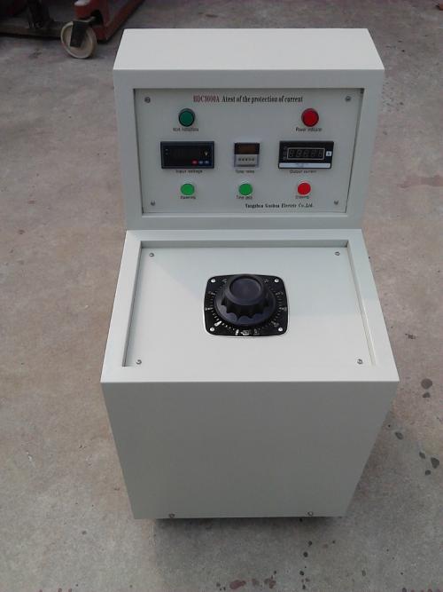
Frequency converters are divided into two major categories by structure: those with 20kW and above are console type, and those below 20kW are portable box type; they are composed of a controller and a filter. In the system, the main function of the frequency converter is to convert the fixed amplitude and frequency of the industrial frequency 380V or 220V sinusoidal AC into a sinusoidal wave with adjustable amplitude and frequency, and provide power for the entire equipment.
The frequency converter has reliable protection functions such as IGBT protection, overcurrent protection, overvoltage protection, discharge protection, and incoming line protection, ensuring the safety of test personnel and test objects.
IGBT protection: When the IGBT current is too high or the temperature is too high, the CPU will stop working until the system returns to normal.
Overvoltage protection: It refers to when the test voltage exceeds the artificially set protection voltage (the protection voltage can be arbitrarily set according to different test voltage requirements), the controller automatically trips, the CPU stops working, and prompts that the system has experienced overvoltage protection.
Overcurrent protection: When the CPU detects that the bus operating current exceeds the IGBT operating current or the IGBT temperature is too high, the CPU will issue an overcurrent protection signal, the device stops working, and the system prompts overcurrent protection through the LCD screen.
Discharge protection: When the test object breaks down, short-circuits, or discharges, the CPU stops working and cuts off the main circuit.
Incoming line protection, low-pass filter: It can not only make the discharge or breakdown current small under steady-state conditions, but also reduce the damage of transient instantaneous current, thereby ensuring the safety of equipment and personnel.
Measurement part: Test personnel can directly read the input voltage, current, current working frequency, output voltage, current of the frequency converter, and the resonant voltage signal applied to the test object from the control panel of the frequency converter.
3.2.2 Excitation transformer
The function of the excitation transformer is to step up the output voltage of the variable frequency power supply to the appropriate test voltage, meeting the requirements of the reactor and load for the test voltage under a certain quality factor (the capacity of the excitation transformer is generally the same as that of the frequency converter). In order to meet the test requirements of different voltage levels and different capacities of test objects, the high-voltage winding of the excitation transformer generally has multiple taps.
3.2.3 High-voltage reactor
The high-voltage reactor L is an important component of the resonant circuit. When the power frequency equals 1/(2π√LCx ), it resonates in series with the test object Cx; the performance of the reactor directly affects the Q value of the system.
3.2.4 High-voltage divider
The high-voltage divider is a high-voltage testing device, which consists of a high-voltage arm C1 and a low-voltage arm C2. The measurement signal is taken from the low-voltage arm C2 and serves as the high-voltage measurement and protection signal.
3.3 Factors determining system configuration parameters
The resonant voltage level and capacity of the system depend on the capacitance C of the test object, the test voltage U, and the test frequency f.
- For cross-linked polyethylene cables, the main factors determining the system configuration are: the voltage level of the cable, the cross-sectional area of the cable, the length of the test cable, and the resonant frequency range required by the cable.
- For GIS, the factors determining the system configuration are: the voltage level of the GIS, the number of intervals in the GIS and the capacitance C of each interval, and the allowable test frequency range of the GIS.
- For transformers, generators, and other equipment, the system configuration depends on the capacity of the test object, the test voltage, the equivalent capacitance C of the test object, the required resonant frequency, and the no-load loss of the test object.