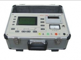
Partial discharge detection is crucial for assessing the insulation condition of power equipment and predicting potential faults. The partial discharge detector detects the presence of discharges by capturing and analyzing electromagnetic radiation or acoustic waves generated by partial discharges. This article will provide a detailed introduction to the working principle, main functions, usage steps, and application scenarios of the partial discharge detector.
Working Principle
When partial discharges occur in the insulation system of power equipment (such as transformers, instrument transformers, etc.) under test voltage, the partial discharge detector captures the discharge pulse current through a coupling capacitor. These pulse currents are picked up by the input unit and amplified by a low-noise preamplifier. Subsequently, the signal passes through a filter amplifier to select the desired frequency band and is further amplified by the main amplifier to reach the required amplitude. The processed signal displays visible discharge pulses on the elliptical scanning baseline of the oscilloscope screen and is simultaneously sent to the pulse peak meter to display its peak value. The time window unit is used to select a working period of the pulse peak meter within each cycle of the test voltage, and during this period, the corresponding display area on the oscilloscope screen is brightened to avoid interference from fixed-phase signals.
Main Functions
High Sensitivity: Capable of detecting weak partial discharge signals.
Wide Frequency Band Combinations: Provides multiple frequency band combinations to adapt to different types of partial discharges.
Auxiliary Zero Marking System: Helps locate discharge events.
Large Screen Oscilloscope Tube: Provides clear display of discharge waveforms.
Large Dynamic Range: Capable of handling a wide range of signal intensities.
Multiple Display Modes: Including elliptical scanning, linear scanning, etc.
Usage Steps
Preparation: Ensure the tester is correctly connected to the equipment under test and set the corresponding parameters.
Host Settings: Adjust various parameters of the tester according to test requirements.
Data Acquisition: Start the tester for data acquisition, observe the graphics on the oscilloscope screen and the readings on the pulse peak meter.
Data Analysis: Analyze the collected data to determine the location and severity of partial discharges.
Test Completion: Turn off the tester and organize the test results.
Application Scenarios
Transformers: Monitor the insulation condition inside oil-immersed or dry-type transformers.
Instrument Transformers: Detect the insulation status of voltage transformers and current transformers.
Cable Terminations and Joints: Assess the partial discharge level of cable terminations and intermediate joints.
High-Voltage Switchgear: Check the health status of internal components in switchgear.
Generators and Motors: Detect abnormal conditions in stator windings, rotor windings, and bearings.
Conclusion
The partial discharge detector is one of the important tools in the maintenance of power equipment. Through regular partial discharge detection, potential insulation problems can be discovered in a timely manner, thereby taking preventive measures to avoid major failures.
References
China Chemical Instrument Network: Technical specifications and parameters related to partial discharge testers.
Renren Library: Relevant guidelines and technical documents on partial discharge detection.
CNKI Encyclopedia: Detailed information and experimental wiring diagrams for partial discharge measurement.