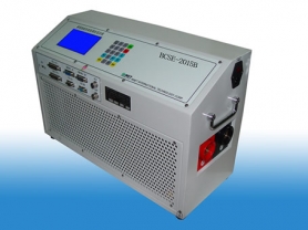
A DC resistance tester is a professional tool used to measure the resistance of conductors in electrical equipment, widely applied in the maintenance and fault diagnosis of transformers, motors, cables, and other equipment in power systems. This article will explore the working principle, key technologies, and applications of DC resistance testers in fault diagnosis.
1. Introduction
DC resistance testers play an important role in the maintenance of power systems. They help technicians accurately measure the resistance of conductors in electrical equipment, thereby determining whether the equipment is in a normal state. By analyzing the resistance values, potential fault points can be effectively identified, ensuring the safe and stable operation of the power system.
2. Working Principle of DC Resistance Tester
The DC resistance tester mainly works based on the following principles:
Four-wire measurement method: Uses two current wires and two voltage wires to eliminate the influence of lead resistance and improve measurement accuracy.
Constant current source: By applying a stable DC current to the device under test, the resulting voltage drop is measured, and the resistance value is calculated.
Data acquisition and analysis: Uses a high-precision data acquisition system to monitor and record test data in real time, and perform analysis and processing.
3. Key Technologies
High-precision measurement: Uses high-precision voltage and current sensors to ensure the accuracy of measurement results.
Wide range measurement: Supports resistance measurement from milliohms to kiloohms.
Automatic compensation: Automatically compensates for errors caused by contact resistance and lead resistance.
Data processing: Built-in data processing software automatically analyzes measurement data and provides intuitive charts and reports.
Remote control: Supports remote control of the tester via wireless or wired methods, facilitating operation in complex environments.
4. Applications in Fault Diagnosis
4.1 Transformer Winding Resistance Test
Background: Transformers are key equipment in power systems, and changes in their winding resistance can reflect the condition of the windings.
Test content: Use a DC resistance tester to measure the resistance of transformer windings.
Test results: If the winding resistance shows significant changes compared to historical data, it may be due to loose windings, poor contact, or damage.
Diagnostic value: Timely detection of changes in winding resistance helps prevent transformer faults and avoid power outages.
4.2 Motor Winding Resistance Test
Background: Motors may experience faults due to winding damage during operation.
Test content: Use a DC resistance tester to measure the resistance of motor windings.
Test results: If the resistance of the motor windings deviates significantly from the nominal value or historical data, it may be due to short circuits or open circuits in the windings.
Diagnostic value: By regularly testing motor winding resistance, potential problems can be detected early, and necessary maintenance measures can be taken.
4.3 Cable Conductor Resistance Test
Background: Cables may experience conductor corrosion or breakage after prolonged use.
Test content: Use a DC resistance tester to measure the resistance of cable conductors.
Test results: If the resistance of the cable conductor