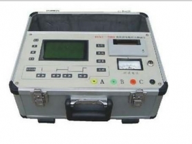
is a specialized instrument used in the power industry to detect key parameters of transformers. It is mainly used to measure the voltage ratio (transformation ratio), vector group (phase relationship), and polarity of transformers, and is a core device in factory tests, acceptance tests, and preventive tests of transformers.
Here is a detailed introduction to this instrument:
1. Main Functions
Measure voltage ratio: Precisely measure the voltage ratio between the high-voltage side and low-voltage side (or medium-voltage side) of the transformer, and determine whether it meets the design values and national standards (usually the error requirement is within ±0.5%).
Determine vector group: Automatically identify and display the vector group label of the transformer (such as Yyn0, Dyn11, YNd11, etc.), and verify whether the winding connections are correct.
Polarity check: Determine the polarity of single-phase or three-phase transformers (subtractive or additive polarity).
Other parameters: Modern high-end instruments can also measure turns ratio, phase angle, unbalance rate, and some models can even measure DC resistance simultaneously.
Fault diagnosis: Through abnormalities in ratio data (such as large deviation in one phase), it can assist in judging whether there are internal faults such as inter-turn short circuits, poor contact of tap changers, or broken windings in the transformer.
2. Working Principle
Traditional ratio bridges use the balance principle, while modern digital ratio and vector group testers mainly use three-phase precision inverter power supplies and high-speed sampling processing technology:
Signal injection: The instrument generates high-precision three-phase sinusoidal voltage (or single-phase voltage) internally and applies it directly to the high-voltage side (or low-voltage side) of the transformer.
Synchronous sampling: Simultaneously collect voltage signals from the high-voltage side and low-voltage side.
Algorithm processing: Use DSP (Digital Signal Processor) to perform Fourier transform (FFT) or other digital filtering algorithms on the collected waveforms to filter out interference and accurately calculate the amplitude ratio and phase difference.
Automatic determination: Based on the calculated phase difference angle, automatically match and display the corresponding vector group.
3. Main Features (Compared to Traditional Bridges)
High degree of automation: One-key operation, automatically completes measurement, calculation, and vector group determination without manual balance adjustment.
Wide measurement range: Wide ratio measurement range (e.g., 0.8 ~ 10000 or even higher), and maintains high accuracy throughout the entire range.
Strong anti-interference capability: Can work stably in complex electromagnetic environments on site.
Good safety: Has reverse connection protection, short circuit protection, overvoltage protection, etc.; some instruments support high-low voltage reverse measurement (i.e., applying voltage from the low-voltage side to measure the high-voltage side), which is convenient for field testing.
Data storage and transmission: Built-in memory can save a large amount of test data, and supports uploading to a computer via USB or Bluetooth to generate reports.
Strong applicability: Not only suitable for ordinary power transformers, but also for Z-type connection transformers, phase-shifting transformers, reactors, and even voltage transformers (PT) ratio tests.
4. Typical Technical Parameters
Ratio measurement range: 0.8 ~ 10000 (varies by model).
Ratio accuracy: Usually ±0.1% or ±0.2%.
Vector group determination: Automatically identify all groups from 0 to 11 o'clock.
Output voltage: Three-phase 0~400V adjustable (auto-adaptive).
Measurement speed: Single-phase <5 seconds, three-phase <15 seconds (including all tap positions).
Tap changer test: Supports multi-position continuous testing of on-load/off-load tap changers (e.g., 9 positions, 17 positions, 27 positions, etc.).
5. Brief Operation Process
Wiring:
Connect the yellow, green, and red (A/B/C) test leads of the instrument to the high-voltage side terminals of the transformer.
Connect the corresponding yellow, green, and red (a/b/c) test leads to the low-voltage side terminals.
Ensure the ground wire is properly connected.
Set parameters: Input the nameplate parameters of the transformer under test (such as rated voltage, expected vector group, number of tap positions, etc.) on the instrument screen.
Start test: Press the "Test" key, and the instrument automatically boosts voltage, samples, and calculates.
Read results: The screen displays the ratio error, vector group, polarity, and other information for each tap position. If the data is qualified, the instrument usually displays "Pass" or a green indicator; if not, it will alarm.
Discharge and disconnect: After the test, the instrument automatically discharges. After confirming no voltage, remove the test leads.
6. Application Scenarios
Transformer manufacturing plants: Routine tests before finished products leave the factory to ensure products meet design specifications.
Power installation companies: Acceptance tests before new transformers are put into operation to verify that no damage occurred during transportation and installation, and that wiring is correct.
Power supply bureaus/operation and maintenance units: Preventive tests for transformers in operation to monitor winding condition and promptly detect inter-turn short circuit hazards.
Maintenance sites: Verification tests after transformer cover lifting maintenance or on-load tap changer maintenance.
7. Precautions
Wiring correspondence: The phase sequence on the high-voltage side and low-voltage side (A-a, B-b, C-c) must strictly correspond; otherwise, it may cause incorrect vector group judgment or measurement failure.
Tap position: Before testing, confirm the position of the transformer tap changer and set the corresponding position in the instrument, especially when performing multi-position tests.
External connections: During the test, disconnect all connections between the transformer and the power grid to ensure the transformer under test is in an isolated state.
Induced voltage: For large transformers, residual charge may exist after the test; wait until the instrument automatically discharges completely before touching the terminals.
Summary
The transformer ratio and vector group tester is a "stethoscope" to ensure the safe operation of transformers. It can quickly and accurately reveal the turns relationship and connection logic of transformer windings, and is one of the most effective means to discover hidden defects such as inter-turn short circuits and wiring errors. With technological development, modern instruments are evolving towards multi-function integration (such as ratio + DC resistance combined machines), wireless, and intelligent diagnosis.